Introduction
Helicopter rotors are marvels of engineering, enabling vertical takeoff, hovering, and agile maneuvering. At the heart of understanding their performance lies momentum theory, a foundational aerodynamic principle that simplifies complex fluid dynamics into actionable insights. This article delves into the application of momentum theory to analyze helicopter rotor performance, from basic principles to practical design implications. We’ll explore how it models rotor flow, derives key parameters, and introduces the Figure of Merit as an efficiency metric. Along the way, we’ll highlight real-world applications, limitations, and future directions—all while keeping the discussion engaging and grounded in accessible
aerodynamics.
Fundamentals of Momentum Theory
Momentum theory, also known as actuator disk theory, originated in the late 19th century with pioneers like William Rankine and William Froude, who applied it to ship propellers. It was later adapted by Nikolai Zhukovsky and Ludwig Prandtl for aircraft propellers and rotors. At its core, momentum theory uses the conservation of mass, momentum,
and energy to analyze the flow through a device that imparts momentum to a fluid, such as a rotor.
The fundamental principle is straightforward: a rotor accelerates a mass of air downward, creating an upward thrust force via Newton’s third law. This is akin to how a fan pushes air to generate breeze. In rotorcraft aerodynamics, momentum theory is invaluable because it provides a simple, first-order approximation of rotor performance without delving
into intricate blade shapes or viscous effects. It’s particularly relevant for helicopters, where rotors must produce lift (thrust) efficiently in hover, forward flight, and maneuvers. By treating the rotor as an “actuator disk”—an infinitely thin surface that uniformly accelerates air— momentum theory estimates induced velocities, power requirements, and efficiency, forming the basis for more advanced analyses.
Modelling Flow Through a Helicopter Rotor
To apply momentum theory to a helicopter rotor, we model the rotor as an actuator disk of area A=πR2 (where R is the rotor radius). Air flows through this disk, gaining downward velocity and creating thrust. The theory assumes an idealized scenario:
Incompressible, inviscid flow: Air is treated as a perfect fluid with no viscosity or compressibility, simplifying calculations.
Uniform, steady flow: The induced velocity is constant across the disk, and there’s no swirl (rotational component) in the wake.
Infinitely thin disk: The rotor is treated as having no thickness, and the pressure jump occurs instantaneously at the disk.
Infinite blades: The rotor is idealized with an infinite number of blades, eliminating discrete blade effects.
Far-field wake: The analysis focuses on the flow far upstream and downstream, ignoring local blade aerodynamics.
These assumptions make the model tractable but introduce simplifications—real rotors have finite blades, tip vortices, and non-uniform inflow.
Deriving Key Performance Parameters
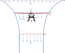
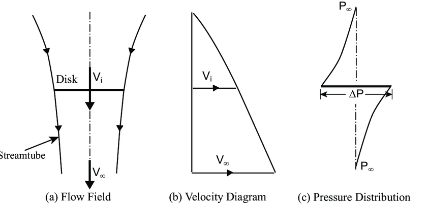
Consider a hovering helicopter: ambient air approaches the rotor from above with zero velocity relative to the rotor. As it passes through the disk, it accelerates downward by an induced velocity vi. Far downstream, in the fully developed wake, the velocity doubles to V! = 2Vi (Figure 1) due to energy conservation (Bernoulli’s principle applied across the
disk).
Figure 1 : Velocity and Pressure Distribution at Hover
1. The mass flow rate through the disk is:
ṁ = ρAVi
where ρ = air density
A = area of the rotor disk (A = πR^2, where R is the rotor radius)
Vi= induced velocity at the disk (downward velocity imparted to the air)
2. By conservation of momentum, the thrust T equals the rate of momentum
change:
T = ṁ (2Vi − 0) = 2ρAVi^2
Solving for Vi: Vi = Sq Root ( T/2ρA)
3. This equation reveals that induced velocity scales with the square root of disk loading T/A – heavier helicopters need more induced velocity for the same rotor size.
4. For forward flight, the model extends to axial flow, where the rotor moves at velocity V relative to the air. The inflow velocity becomes V+Vi at the disk, and the wake velocity is V+2Vi. Thrust is then:
T = 2ρAVi(V + Vi)
This forms a quadratic equation for Vi , solved iteratively.
5. Momentum theory shines in quantifying Thrust, Induced power, and Efficiency—crucial for assessing rotor viability.
Thrust
6. As derived above, thrust T = 2ρAVi^2 in hover. This shows thrust depends on induced velocity squared, emphasizing efficient airflow acceleration. In practice, designers use this to size rotors: for a given thrust (e.g., to lift a 10,000 kg helicopter), a larger A reduces Vi and power needs.
Induced Power
7. Power is the energy imparted to the airflow per unit time. The induced power Pi
is the kinetic energy rate in the wake:
Pi = TVi = 2ρAVi^3
Alternately Pi = T Sq Root (T/2ρA)
8. This is the ideal induced power—the minimum required for a given thrust. Real rotors consume more due to losses, but this sets a benchmark. In forward flight, Pi=T(V+Vi), reducing as V increases (less induced velocity needed).
Rotor Efficiency
9. Efficiency in momentum theory often compares actual power to ideal. For propellers, it’s η=TV/P, but for rotors, it’s nuanced. In hover, there’s no forward speed, so efficiency is zero in a propulsive sense—yet we care about how effectively power generates thrust. This leads to the concept of Figure of Merit.
The Figure of Merit: A Measure of Rotor Efficiency
10. The Figure of Merit (FM) is a dimensionless parameter that quantifies the efficiency of a helicopter rotor in hover. It is defined as the ratio of the minimum (ideal) power required to produce a given thrust (as predicted by momentum theory) to the actual power consumed by the rotor. FM = Ideal Power (Momentum Theory)/Actual Power Required
Mathematical Formulation
FM = T Sq Root (T/2ρA)/Pactual
Where:
T = thrust
ρ = air density
A = rotor disk area
Pactual = actual power required by the rotor (includes induced power plus profile power (drag on blades) and other losses).
Factors Influencing FM
- Blade design: Twist, airfoil shape, and solidity (blade area fraction) affect uniformity of induced flow. Optimal twist maximizes FM by matching local velocities.
- Operating conditions: High disk loading lowers FM due to increased Vi and losses. Tip speed ratio and altitude (via ρ) also play roles—lower density at high altitudes reduces FM.
- Wake effects: Real wakes have tip vortices, reducing effective area and FM by 10-20%.
- Non-uniform inflow: The actual induced velocity varies across the disk. In different conditions, FM drops in forward flight due to asymmetric loading, but climbs in ground effect (reduced Vi).
- Mechanical losses: Power is lost in the transmission and bearings.
- Typical FM values for helicopter rotors in hover range from 0.65 to 0.75, with 1.0 representing the ideal, lossless case(impossible in reality).
11. FM’s significance lies in its role as a design metric: higher FM indicates better hover performance, crucial for missions like search-and-rescue where hovering efficiency saves fuel.
Practical Applications in Rotor Design and Performance Optimization
Design Implications
- Blade Shape and Airfoil Selection: Momentum theory guides the selection of blade planform and airfoil to maximize FM.
- Disk Loading: Lower disk loading (thrust per unit area) generally leads to higher FM and lower induced power.
- Hover Performance: Momentum theory is used to estimate hover ceiling and power requirements for different rotor sizes and configurations.
Performance Optimization
- Variable Rotor Speed: Adjusting rotor speed to match flight conditions can improve FM and reduce fuel consumption.
- Advanced Blade Designs: Features like swept tips and active twist can reduce tip losses and improve FM.
Designers use it for initial sizing: for the Boeing CH-47 Chinook’s tandem rotors, momentum calculations helped optimize disk area for heavy-lift hover efficiency, achieving FM around 0.75.
In the Eurocopter (now Airbus) EC135, momentum theory guided blade twist adjustments to minimize induced power, improving fuel efficiency by 10-15% in hover. Case studies from NASA tests on scaled rotors show FM improvements via tip shapes that reduce vortex losses, validated against momentum predictions.
The UH-60 Black Hawk’s main rotor was designed with momentum theory as a baseline, then refined using blade element theory and wind tunnel testing. The rotor achieves an FM of approximately 0.72 in hover, balancing efficiency with structural and operational constraints.
Software like NASA’s OVERFLOW integrates momentum-based models with CFD for hybrid optimization. In electric VTOL (eVTOL) designs like Joby Aviation’s, momentum theory estimates battery needs for hover, influencing rotor diameter and count.
Limitations and Advancements
While powerful, momentum theory has limitations: it ignores viscosity, leading to underestimation of profile drag (real power is 20-50% higher). Uniform flow assumptions fail for non-axial flight or ground effect, and it doesn’t capture blade element details like stall or compressibility at high speeds.
- Blade Element Momentum Theory (BEMT): Combines momentum with blade aerodynamics for local lift/drag.
- Vortex Theory: Models wake vortices for better induced velocity predictions.
- Computational Fluid Dynamics (CFD): Resolves full Navier-Stokes equations, though computationally intensive.
- Advancements: Machine learning optimizes parameters beyond momentum limits, as in DARPA’s rotor design programs.
Conclusion
Momentum theory remains a cornerstone of helicopter rotor analysis, providing a clear, physics-based framework for understanding thrust generation, power requirements, and efficiency. While its assumptions limit its accuracy for detailed design, it serves as a vital starting point for more advanced methods. The Figure of Merit, derived from momentum theory, continues to be a key metric in rotor performance evaluation and optimization. As computational tools and experimental techniques advance, engineers can build upon the foundations of momentum theory to design ever more efficient and capable rotorcraft.
References
Leishman, J. G. (2006). Principles of Helicopter Aerodynamics. Cambridge University Press.
Johnson, W. (1980). Helicopter Theory. Dover Publications.
Padfield, G. D. (2007). Helicopter Flight Dynamics. Blackwell Publishing.

Be Safe. Fly Safe.